ARIEL Local Area Networking (LAN) Experiments
The experiments are described in chronological order, starting with very elementary ones. Your understanding of each experiment may rely on your having completed the previous one, so if the explanation is not clear, check back to the previous experiment to get a starting point.
You can download a zip file of all five LAN experiments here. After downloading, unzip and put all the experiments in a convenient directory on your local host machine.
Links:
LAN 1. Virtual Computer – MAC Address
LAN 4. Virtual Local Area Networks (VLANS)
LAN 1. Virtual Computer – MAC Address
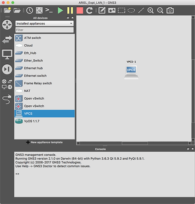
The first experiment is the simplest possible. Open GNS3 and click on the icon of the collection of four different device types in the left margin (browse all devices), select ‘installed appliances’ from the dropdown list to see several simple appliances that come pre-installed. Click on the Virtual Computer VPCS and drag and drop it in the work area. Click on the green “Start Triangle”. After starting, right-click on the Virtual PC and select “Console”. You should now have a terminal window into your Virtual PC. Try it out – see what it can do.
In the console enter the command ‘help’ to see a full list of commands. Try ‘arp’ to see the Address Resolution Protocol cache – at this stage it should be empty. Try ‘show ip’ which shows the information for IP (Internet Protocol) and other settings. Scan down the list for the MAC address – this is the Medium Access Control address – in this case it is an Ethernet address (by far the most common). Don’t worry about all the details shown.
Sample Output:
VPCS-1>
show ip
NAME
: VPCS-1[1]
IP/MASK
: 0.0.0.0/0
GATEWAY
: VPCS-1[1]
DNS
:
MAC
: 00:50:79:66:68:00
LPORT
: 10000
RHOST:PORT
: 127.0.0.1:10001
MTU
: 1500
Discussion:
Back to ARIEL Local Area Networking (LAN) Experiments
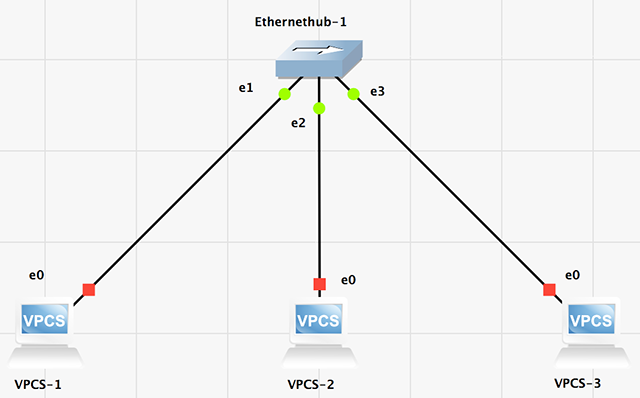
From Experiment LAN_1, drag and drop two more VPCS into the work area. Drag and drop a pre-installed Ethernet Hub into the work area. Click on the link icon, and connect each of the VPCS to a different port* on the Ethernet Hub.
* Definition of “port” In networking, the word “port” is tricky – it has different meanings in different contexts. When talking about devices, it refers to a physical input or output on the device. You can physically plug an optical or copper cable, with a suitable connector, into a compatible port. Of course, if the device is virtualised it has no physical ports, but we still refer to its virtual inputs and outputs as ports. Whether they are physical or virtual, for each port there may be several distinct interfaces – logical connection points served by that single port. Even this distinction is sometimes blurred. For example, we talk of the “loop-back port” which is more like an interface than a port.
In the context of higher layer protocols the word “port” is interpreted differently. In the Transport Layer, 16-bit port numbers are used to address separate applications. A Transport Layer segment within an IP Packet (possibly within an Ethernet Frame) is directed to an interface by the IP address, and then, within the host served by that interface, it is directed to an application by the port number. The application connects to the port by a software “socket”.
In a way, the two meanings are related – in both cases a port is the thing on which the transmission comes in and goes out.
Tip: if you want your layout to look neat, turn on ‘Snap to Grid’ and ‘Show Grid’ under the menu ‘Edit’, ‘Preferences’. If you want to, you can take a screenshot by clicking on the camera icon in the top bar.
Click on the green triangle to start the emulation. Then click on the ‘>_’ icon to start up a console for all three VPCS. There is no console for the Ethernet Hub because it is a “dumb” device. An Ethernet hub is sometimes described as a “bus in a box”, where “bus” refers to a length of (originally coaxial) cable into which end devices may tap.
Begin here if you downloaded: ARIEL_LAN_02.gns3project.
Check that all three ARP tables are empty. Then, without being concerned about the details or the reason, assign an IPv4 address to each VPCS. The command for VPCS-1 is:
ip 192.168.1.1
Then for VPCS-2 and VPCS-3 use “ip 192.168.1.2", and “ip 192.168.1.3". Note what happens if you deliberately make a mistake and try to assign 192.168.1.1 to VPCS-3 as well as VPCS-1.Start a packet capture on “Link 1” – the link from VPCS-1 to the Ethernet Hub – right click on the link and select ‘Start capture’. Click on ‘OK’ for the default settings.
Using the IP addresses, we can run the program “ping” to generate some traffic. In the console for VPCS-1 enter the command ‘ping 192.168.1.2’ to cause VPCS-1 to “ping” VPCS-2.
The first two packets captured are ARP – Address Resolution Protocol – packets. This allows the devices in the network to learn which IP address is associated with which MAC address. The first packet is a broadcast, saying:
“Who has 192.168.1.2? Tell 192.168.1.1”
The Ethernet hub sends this broadcast out on every port except the one it came in on. At this stage, only VPCS-2 knows that its IP address is 192.168.1.2. It receives the broadcast packet and sends a reply to the originator of the request, giving its MAC address. The corresponding MAC and IP addresses are then stored temporarily in the ARP table in the interface of the PC (why temporarily?).
After the ARP procedure, you should see five pairs of packets – each pair comprising an “echo request” and an “echo reply”. The time between sending the echo request and getting the echo reply is a measurement of the Round Trip Time (RTT).
Now enter ‘arp’ commands again, and carefully check the information in each ARP table. Can you explain what you see? If the ARP tables are empty, try the ping again and check the ARP tables quickly, before the entries in the tables expire. The tables are, in fact, caches.
Now quickly repeat the ping from VPCS-1 to VPCS-2. Do you see any ARP packets? Can you explain? If you wait a couple of minutes and ping again, do you see any ARP packets. Can you explain?
Wait a couple of minutes for all entries in all ARP caches to expire, then ping from VPCS-2 to VPCS-3. Watch for packets being captured on the link from VPCS-1 to the Ethernet Hub. Would you expect to see any packets on this link, since it has no direct connection to either VPCS-2 or VPCS-3. Explain what you see.
Are you confident you could explain what packets you expect to be captured on each link, and what entries will be in each ARP table, as each node pings any other node?
Sample Output:
VPCS-1> ip 192.168.1.1
Checking for duplicate address...
PC1 : 192.168.1.1 255.255.255.0
VPCS-1> ping 192.168.1.2
84 bytes from 192.168.1.2 icmp_seq=1 ttl=64 time=1.035 ms
84 bytes from 192.168.1.2 icmp_seq=2 ttl=64 time=1.102 ms
84 bytes from 192.168.1.2 icmp_seq=3 ttl=64 time=0.948 ms
84 bytes from 192.168.1.2 icmp_seq=4 ttl=64 time=1.012 ms
84 bytes from 192.168.1.2 icmp_seq=5 ttl=64 time=0.867 ms
VPCS-1> arp
00:50:79:66:68:01 192.168.1.2 expires in 63 seconds
Wireshark Packet Capture Files:
Packets that were captured on Link 1 while VPCS-1 pings VPCS-2: ARIEL_LAN_02_Capture_01.pcapngPackets that were captured on Link 1 while VPCS-2 pings VPCS-3: ARIEL_LAN_02_Capture_02.pcapng
Discussion:
Back to ARIEL Local Area Networking (LAN) Experiments
Repeat the procedure for experiment 2 – confirm or configure IP addresses, then ping from host to host and examine the ARP tables.
Explain the changes you observe from Experiment 2 to Experiment 3.
Wireshark Packet Capture Files:
Packets that were captured on Link 1 while VPCS-1 pings VPCS-2: ARIEL_LAN_03_Capture_01.pcapngPackets that were captured on Link 1 while VPCS-2 pings VPCS-3: ARIEL_LAN_03_Capture_02.pcapng
Discussion:
Back to ARIEL Local Area Networking (LAN) Experiments
To begin, here is a riddle: What is the difference
between
“invisible” and “virtual? Answer: if something is invisible you CANNOT see
it, even though it IS there – if something is virtual you CAN see it,
even though it is NOT there.
A Virtual Local Area Network, or VLAN, is a virtual
network
within a physical network. It
operates
as a separate LAN, but it exists only in the form of tags that are added
to
Ethernet frame headers. The
devices in
the network can “see” the VLAN even though the VLAN is not there,
physically.
From https://en.wikipedia.org/wiki/IEEE_802.1Q:
IEEE 802.1Q, often referred to as
Dot1q,
is the networking standard that supports VLANs on an Ethernet network.
The
standard defines a system of VLAN tagging for Ethernet frames and the
accompanying procedures to be used by bridges and switches in handling
such
frames.
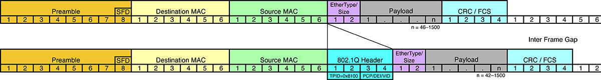
This diagram from https://en.wikipedia.org/wiki/IEEE_802.1Q shows how the Dot1q header, or VLAN tag, is slotted in after the Source
MAC
address.
In this experiment, you will configure one physical LAN
with
two VLANs, and then demonstrate what is meant by: “You can see the VLAN even though
it is not there, physically.”
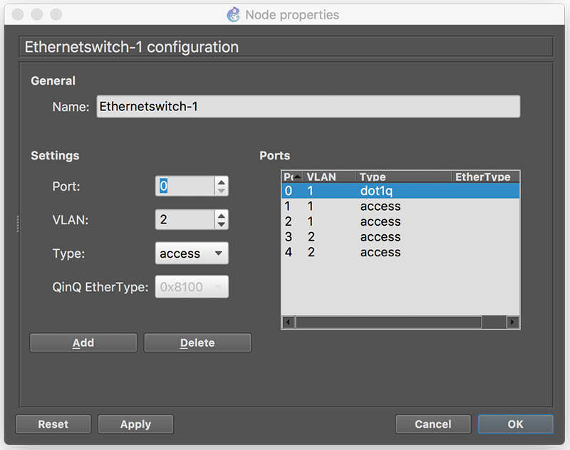
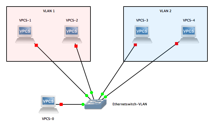
Start a new project with one Ethernet Switch and four VPCS terminals. BEFORE making any connections, right click on the Ethernet Switch icon and select the ‘Configure’ option. The ports on the Ethernet Switch can be modified by double clicking on the port then entering the required options. IMPORTANT: click “Add” after you have made modifications for each port. If you have trouble with a port, “Delete” that port and “Add” a new one with the same number, configured as you prefer. Finally, if you like, you can “Delete” all the remaining ports you don’t need. Your configuration should end up like the Figure above. Note that port 0 is designated as dot1q and VLAN 1 – this implies that VLAN1 is the “Native VLAN”.
Spin up 5 VPCs, configured with IPv4 addresses:
VPCS-0>
ip 192.168.1.100
VPCS-1>
192.168.1.1
VPCS-2>
192.168.1.2
VPCS-3>
192.168.1.3
VPCS-4>
192.168.1.4
Here is a screenshot of my workspace, with added notes for clarity:
Discussion:
Back to ARIEL Local Area Networking (LAN) Experiments
What might happen if the switching
topology became a little more complex. Suppose Electrical Engineering (denoted “E”), and Mechanical
Engineering
(denoted “M”), and Chemical Engineering (denoted “C”) all had their own
Ethernet Segment, and one Ethernet Switch each. Then suppose each department wanted to connect to the other two. We would end up with a triangle of three
Ethernet Switches denoted E, M, and C. If the link from E to M is down, we would want the E-to-M traffic
to go
from E via C to M, rather than just getting dropped. But, that degree of flexibility implies the
possibility of a routing loop coming into existence. If all three links are working, and traffic
from E to M is routed via C, perhaps also the traffic from C to M is
routed via
E. So where does E-to-M
traffic
flow. First it goes via C
on the way to
M. At C it is destined for
M, so it is
sent via E – back to where it started. In principle, the process continues indefinitely.
Most Switches and Bridges are too
smart
to allow infinite loops to develop. They
are often referred to as “Learning-Switches” and “Learning-Bridges”. They implement a Spanning Tree Protocol, with
the aim of ensuring that, at any time, there is just one path from any
Ethernet
segment to any other segment. The
existence
of one and only one path is the definition of a “tree network”; the
“spanning” term just means that all nodes are included – no-one is
unreachable. They achieve
the tree topology be effectively
banning some paths.
The disadvantage of a tree is that
any
single link failure results in the tree being cut into two disconnected
parts. As links go down or
up over time,
the paths may have to change, but the ideal is to avoid routing loops,
even
transient ones.
The built-in Ethernet Switch in
GNS3 does
not implement STP, therefore we will move on to Open vSwitch (see http://openvswitch.org/)
for our next
experiment. Even Open
vSwitch does not
have Spanning Tree Protocol, or the more modern Rapid Spanning Tree
Protocol,
enabled by default – we will have to enable one or the other through a
Command
Line Interface (CLI).
Later we will discover by
experiment that
Open vSwitch is an SDN (Software-Defined Networking) device – it can be
controlled comprehensively from an external controller, instead of
relying on a
CLI. Check out the Open
Daylight web
site (https://www.opendaylight.org/)
for a preview. By the way,
both Open
Daylight and Open vSwitch come under the Linux Foundation (https://www.linuxfoundation.org/). While
you are there, check out the free
MOOCs available from the Linux Foundation.
We begin with three Open vSwitches
and
three VPCs. Connect each
VPC (1 through
3) to the corresponding Open vSwitch, but do not use interface eth0 on
any of
the switches, because that interface is reserved for management. Connect Open vSwitch-1 to Open vSwitch-2, and
Open vSwitch-2 to Open vSwitch-3, but do not complete the loop from 3 to
1.
Start the emulation, and spin up consoles for all
devices. Configure the usual
– or
unusual J – IPv4 addresses for the PCs, and save the configuration. Now try pinging. Hopefully
you will find that every PC can
ping every other PC.
Check to see if the Round Trip
Times
between 1 and 3 tend to be greater than the times between 1 and 2 – why
would
that be so? Let’s fix that
by adding a
link from Open vSwitch-1 directly to Open vSwitch-3 – what could go
wrong? Does the additional
link speed up the round
trip? What happened?
In the console for each Open
vSwitch
enter the following three commands to enable STP – Spanning Tree
Protocol:
ovs-vsctl
set Bridge br0
stp_enable=true
ovs-vsctl
set Bridge br0 other_config:stp-priority=0x7800
ovs-vsctl
set Port eth0
other_config:stp-path-cost=10
Discussion:
Back to ARIEL Local Area Networking (LAN) Experiments